FPGA Labs
An FPGA is a flexible chip whose internal logic can be configured to realize the digital circuit we want. Unlike an ASIC, which is manufactured for one fixed design, an FPGA lets us write a circuit in SystemVerilog, load it onto the chip, test it, and replace it with another circuit later.
For hands-on experience, we highly recommend buying the inexpensive Tang Nano 20K from either Amazon, or AliExpress. On AliExpress, carefully choose Bundle: Nano 20K No header, and triple-check the delivery address before checkout.
Overview
We will turn our simulated SystemVerilog circuits into configurations that run
on a real FPGA. The board is described in the official Tang Nano 20K
datasheet.
It uses a Gowin GW2AR-18 FPGA; the board overview
has additional hardware details.
The general FPGA flow is as follows:
Design the circuit in SystemVerilog. See our SystemVerilog RTL.
Test it in simulation using a SystemVerilog testbench:
make sim DESIGN=<design>.Translate it into a bitstream (the configuration loaded onto the FPGA) using our
fpga.mkbuild flow:make bitstream DESIGN=<design>.Program the FPGA with openFPGALoader Web.
Interact with the circuit on the FPGA: press its buttons, observe its LEDs, or send and receive data from your computer.
Module Heirarchy
We have built the following module hierarchy to help you quickly implement your own designs in the FPGA.
Your SystemVerilog Design: e.g.
full_adderAn idealized FPGA interface:
board_glueCheck out the skeleton of
board_gluehere.Each of your designs (e.g.
full_adder) need to be wrapped in a module namedboard_gluein a file namedfull_adder.f(note that file and module names are different), placed inmaterial/fpga/tang_nano_20k/top_glue/*/full_adder.f.The inputs and outputs of
board_gluerepresent an ideal FPGA: active high LEDs, clean buttons…etc.
Topmost module:
board_top.svYou should not change this file.
This module instantiates
board_gluemodule. Since theboard_glues of all designs have the same interface, this module can accept any of them. When you domake bitstream DESGIN=full_adderfpga.mkselects theboard glueintop_glue/reference/full_adder.sv.This module abstracts away the real world behaviors of an FPGA to present an idealized interface to
board_glue. Some of these abstractions are:Control reset signal when powering on
Active-high LEDs
The LED lights on the FPGA are electronically wired to be active low. They light up when
LED[i]=0. This module inverts that into active high, so they light up when you doLED[i]=1inside theboard_glue.Button synchronization and debouncing
When you press a button, mechanically the contacts touch and break several times due to vibrations. This causes the
btn[i]input to oscillate from0to1and back many times before settling onbtn[i]=1. Debouncing logic inboard_glueobserves it for a long time, and only givesbtn[i]=1to theboard_glueafter everything settles.UART input synchronization
The
RXinput of UART is not synchronized to any clock (it is in the name). This causes weird behavior if you try to sample it at a clock edge.board_topsynchronizes it to the clock by registering it twice and gives to theboard_glue.GPIO
Most General Purpose Input Output (GPIO) pins of the FPGA can act as either input or output, and are hence declared as
inoutports. Dealing withinoutports is error-prone, since driving the same inout port from the FPGA (output) and from the outside (input) at the same time can lead to short circuit.board_topconverts that intoinput,outputandoutput_enableports, which helps you avoid human error.
Environment Setup
The examples use two separate environments:
Build
.fsbitstreams and train the neural network inside the course Docker container.Run the Python UART, audio, and camera tools outside the container in a Conda environment.
Complete the Docker setup first. If you have not cloned the repository yet, run:
git clone https://github.com/abarajithan11/digital-design
cd digital-design
All commands below assume that your terminal is in this digital-design
directory.
1. Full Adder on the FPGA
During discussion, we put the up_counter on the FPGA.
The full_adder follows the same flow.
If you have done the up_counter, you may skip this.
1.1 Design the Circuit
1.2 Test in Simulation
Run the
tb_full_adder.sv
testbench inside the container:
make enter
make sim DESIGN=full_adder
exit
1.3 Translate to a Bitstream
Build the bitstream (= FPGA configuration) inside the container:
make enter
make bitstream DESIGN=full_adder
exit
This invokes the commands in fpga.mk, which read full_adder.f,
removes simulation-only sources, adds board_glue and the fixed
board_top.sv,
then runs the open-source Apicula flow (yosys → nextpnr-himbaechel → gowin_pack) to generate material/fpga/tang_nano_20k/build/full_adder/full_adder.fs.
1.4 Program the FPGA and Interact with your design
Windows 11: one-time WebUSB setup
There are two interfaces on the board: interface 0/A is JTAG programming, and interface 1/B is UART. Keep them separate during the setup.
Download and run Zadig. It is portable and does not need to be installed.
Connect the Tang Nano 20K to Windows.
In Zadig, select Options → List All Devices.
Select Dual RS232-HS / USB Debugger (Interface 0) or Interface A.
Select WinUSB, then click Replace Driver.
Do not replace the driver for interface 1/B; that is the UART used by the Python scripts.
To program a bitstream:
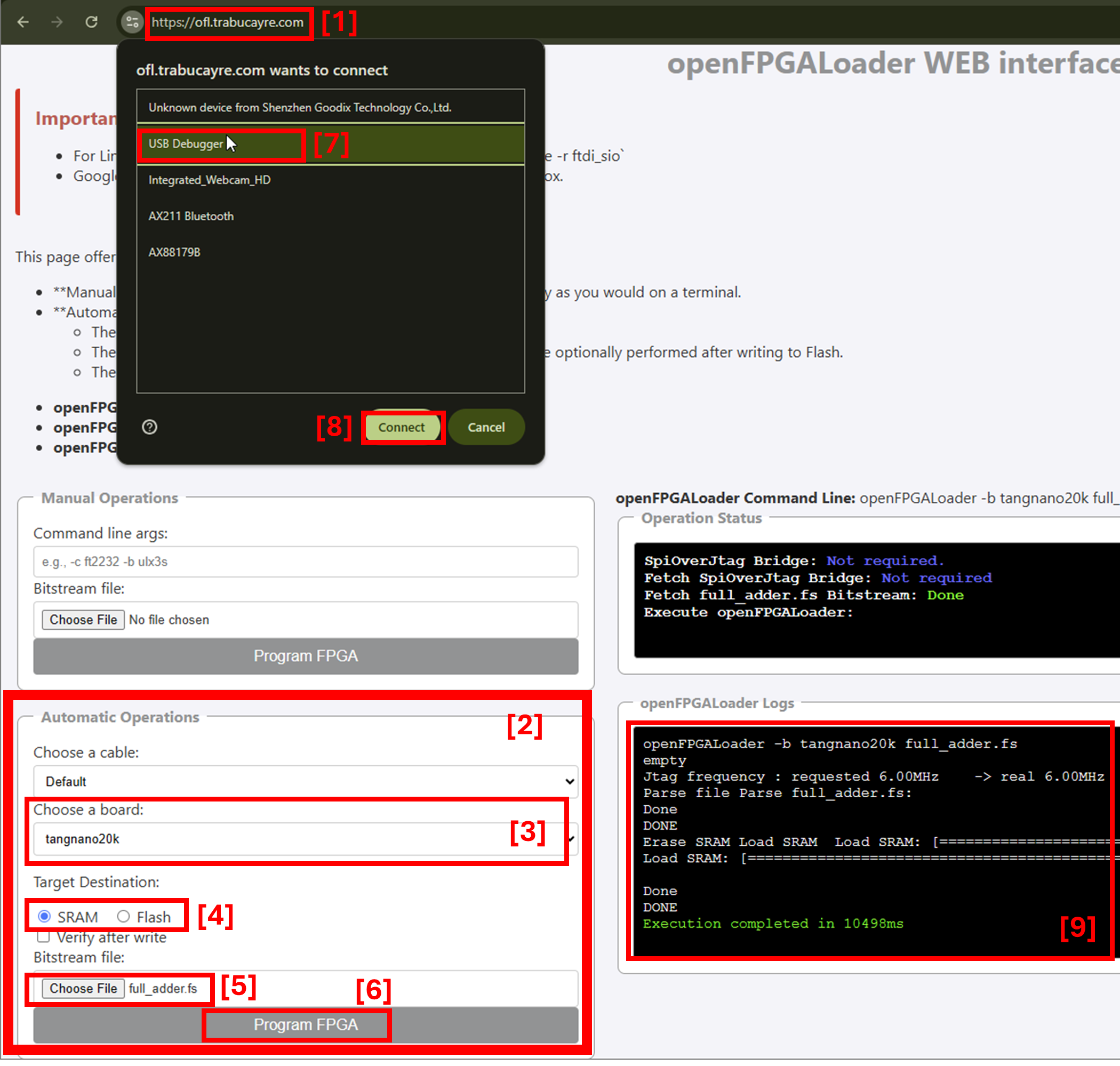
Open openFPGALoader Web in a Chrome-based browser. Firefox does not support WebUSB.
Go to the section Automatic Operations.
Leave the cable as default, and select Tang Nano 20K as the board.
Select SRAM for a temporary configuration or Flash to keep the configuration after power is removed.
Choose the design’s
.fsfile. For this example, usematerial/fpga/tang_nano_20k/build/full_adder/full_adder.fs.Click Program FPGA.
The first time you do this, it opens this dialog box. Select “USB Debugger” and click “Connect”. Note, Firefox does not support WebUSB.
A successful run ends with
Execution completed.
Press S1 and S2 to change the full adder’s two inputs. LED0 shows the sum and LED1 shows the carry output.
You can try other simple designs in exactly the same way:
and_gate: RTL · board_gluenot_gate: RTL · board_gluexor_gate: RTL · board_gluemux: RTL · board_gluedecoder: RTL · board_glue
You can wrap your own module in the same way: add its .f file and copy
top_glue/_skeleton.sv
to create its matching board_glue.
The reusable FPGA files are organized as follows:
material/fpga/tang_nano_20k/
  common/board_top.sv                    fixed board wrapper
  common/board.cst                       fixed pin constraints
  common/fpga.mk                         bitstream build rules
  top_glue/{cpu,reference,system}/       one board_glue per design
  build/<design>/                        generated files; not committed
material/designs/{cpu,reference,systems}/<design>.f
FPGA defaults to tang_nano_20k. A design can be built when it has both a matching .f source list and board_glue.
The build ignores tb_* and vip_*
simulation sources. From inside the container, make bitstream_all builds every design that has both files.
2. UART Serial: Talking to your computer
We will now implement more advanced designs on the FPGA and communicate with them from the computer. We use UART (Universal Asynchronous Receiver/Transmitter), a simple serial protocol supported by almost every system. UART is easy to use but relatively slow. We will cover the protocol and its circuits in the lectures.
Computer and board UART details
On the computer, Python can send and receive UART data through the
pyserial library. Later examples
also need numerical and audio libraries, so we install everything together in
a Conda environment.
The board’s USB-to-UART bridge operates at 2 Mbaud, has a 32-byte buffer, and has no hardware flow control.
At the board’s 54 MHz system clock,
the UART circuits use CLKS_PER_BIT=27.
The echo and FIR designs use a two-entry
skid_buffer,
while the host scripts transfer at most 32 bytes at a time and drain replies so
the bridge does not silently drop data.
2.1 Install Miniconda
Open the instructions for your operating system. If Conda is already installed
and conda --version works, skip to the next section.
Ubuntu
Follow the official Miniconda Linux installation guide. Download the installer that matches your processor.
Accept the default install location. When asked whether to initialize Conda, answer
yes.Close and reopen the terminal, then check the installation:
conda --version
macOS
Follow the official Miniconda macOS installation guide. Choose the installer that matches your Mac’s processor.
When asked whether to initialize Conda, answer
yes.Close and reopen Terminal, then check the installation:
conda --version
Windows 11
Install and run Conda directly on Windows. WSL is still used for the course Docker container, but it is not used for the Python environment or UART scripts.
Follow the official Miniconda Windows installation guide.
Choose Just Me, keep the default install location, and do not select Add Miniconda3 to my PATH environment variable.
Find Anaconda Prompt (Miniconda3) in the Start menu, right-click it, and select Run as administrator. Check the installation:
conda --version
Use the Administrator prompt when creating or updating the environment. After
that, use a regular Anaconda Prompt to activate the environment and run Python
scripts. Change to the Windows location of your digital-design checkout
first.
2.2 Create the Environment
On Windows, run the conda env create command below from the Administrator
Anaconda Prompt opened in the previous section. Ubuntu and macOS users should
use their regular terminal.
conda env create -f python-setup/tang-basic.yml
conda activate tang-basic
You only need to create an environment once. You do need to activate it in each new terminal before running a lab script.
Check that the basic packages and the expected Python version are available:
python --version
python -c "import numpy, scipy, serial; print('FPGA Python environment is ready')"
The version should be Python 3.11, and the second command should print the ready message without an error.
2.3 Run the UART Echo Test
This test checks if your computer can talk to your hardware in the FPGA.
Simulate
uart_echo, then build its bitstream inside the Docker container:make enter make sim DESIGN=uart_echo make bitstream DESIGN=uart_echo exit
In Chrome, program
material/fpga/tang_nano_20k/build/uart_echo/uart_echo.fs.Activate the basic environment and run the loopback test:
conda activate tang-basic
python material/py/fpga_uart_echo.py
If the Python script cannot find or open the board, see UART access troubleshooting.
The test should finish with:
PASS: echoed 4096 bytes with no loss.
4. FIR Filter
The FIR filter examples send audio samples to sys_fir_filter over UART and
receive the filtered samples back. Start with a saved audio file, then try the
same circuit with live microphone audio.
4.1 Offline File Test
This test sends the included audio file through the FPGA and compares every
output sample with the reference file. The script reads (or downloads)
material/data/chill_sub.wav, writes material/data/fpga_out.wav, and compares
it with material/data/bass_only_8bit.wav. These paths are resolved relative
to the script, so it can also be invoked from another directory.
Simulate
sys_fir_filter, then build its bitstream inside the Docker container. The simulation generates the files needed by the example:make enter make sim DESIGN=sys_fir_filter make bitstream DESIGN=sys_fir_filter exit
In Chrome, program
material/fpga/tang_nano_20k/build/sys_fir_filter/sys_fir_filter.fs.Activate the basic environment and process the included WAV file:
conda activate tang-basic
python material/py/fpga_fir_offline.py
If the Python script cannot find or open the board, see UART access troubleshooting.
The test should finish with a message similar to:
PASS: all 735000 samples match .../material/data/bass_only_8bit.wav.
Both scripts detect the Tang Nano UART port automatically. If more than one serial port is connected, select it explicitly:
python material/py/fpga_fir_offline.py --port /dev/ttyUSB1
Use the path printed by your system; on macOS it will usually begin with
/dev/cu.usbserial-, and on Windows it will look like COM5.
4.2 Live Audio Test
This example records your microphone, sends the audio through the FPGA, and plays the filtered result through your selected output device. You should hear mostly bass because the FPGA is running a low-pass filter.
Simulate
sys_fir_filter, then build its bitstream inside the Docker container. The simulation generates the files needed by the example:make enter make sim DESIGN=sys_fir_filter make bitstream DESIGN=sys_fir_filter exit
In Chrome, program
material/fpga/tang_nano_20k/build/sys_fir_filter/sys_fir_filter.fs.Connect headphones and start at a low volume. Using speakers near the microphone can create loud feedback.
Activate the basic environment and list the available audio devices:
conda activate tang-basic
python material/py/fpga_fir_live_audio.py --list
If your default microphone and output are correct, start the live filter:
python material/py/fpga_fir_live_audio.pyIf the Python script cannot find or open the board, see UART access troubleshooting.
Press Ctrl+C to stop.
To select different devices, pass the number shown by --list or a unique part
of each device name:
python material/py/fpga_fir_live_audio.py --input 2 --output 5
The UART port can be selected in the same command when automatic detection is not possible. For example, on native Windows:
python material/py/fpga_fir_live_audio.py --port COM5 --input 2 --output 5
Live-audio troubleshooting by operating system
Ubuntu: Select the intended microphone and headphones in Settings →
Sound. If
--list reports that PortAudio sees no devices, install the system audio
support and try again:
sudo apt update
sudo apt install libportaudio2 libasound2-plugins
If the Conda interpreter still cannot see the devices, install the Ubuntu Python audio packages and run only the live-audio script with the system interpreter:
sudo apt install python3-numpy python3-serial python3-sounddevice
/usr/bin/python3 material/py/fpga_fir_live_audio.py --list
/usr/bin/python3 material/py/fpga_fir_live_audio.py
macOS: The first run may request microphone access. If it was denied, open
System Settings → Privacy & Security →
Microphone
and allow access for the terminal application you are using. Run the --list
command again after changing the permission.
Windows 11: Open Settings → Privacy & security →
Microphone
and enable Microphone access and Let desktop apps access your
microphone. Select the intended microphone and headphones in Settings →
System → Sound, then run the --list command again.
5. CPU
Check out our small CPU designed in 40 lines of SystemVerilog here. This example loads a small program into the CPU on the FPGA over UART, runs it, and sends the data memory back to the computer.
program = [
   [LOAD,  2, 0x02],       # r2 (counter) = dmem[2] = 10
   [LOAD,  1, 0x01],       # r1 (one)     = dmem[1] = 1
   [LOAD,  0, 0x00],       # r0 (sum)     = dmem[0] = 0
   [ADD,   0, 0, 2],       # r0 += r2
   [SUB,   2, 2, 1],       # r2 -= r1
   [JNZ,   2, 0x03],       # loop to imem[3] while r2 != 0
   [STORE, 0, WATCH_ADDR], # dmem[WATCH_ADDR] = r0  (= 55)
]
The program computes 1 + ... + 10 and stores the result in dmem[4]. You may write your own program in the assembly specified here.
Simulate
cpu_fpga, then build its bitstream inside the Docker container:make enter make sim DESIGN=cpu_fpga make bitstream DESIGN=cpu_fpga exit
In Chrome, program
material/fpga/tang_nano_20k/build/cpu_fpga/cpu_fpga.fs.Activate the basic environment and load the example program:
conda activate tang-basic
python material/py/fpga_program_cpu.py
If the Python script cannot find or open the board, see UART access troubleshooting.
Press S1 when prompted. The CPU runs at about one instruction per second, and the LEDs show the opcode. Hold S2 to show the low six bits of
dmem[4]instead.
When the run finishes, the script prints the returned data memory. The final line should be:
dmem[4] = 55 (sum(1..10) should be 55)
6. Neural-Network Accelerator
Assignment 4 combines the UART and neural-network blocks into sys_nn.
The complete path taken by the data
Handwritten image on PC / from webcam
Python (fpga_nn.py)
preprocessing
pyserial
USB
FPGA
USB-to-UART bridge
UART RX
dense 1
quant_ReLU 1
dense 2
output qReLU
UART TX
USB-to-UART bridge
Your PC
USB
Python: pyserial → prediction
The network maps 81 quantized pixels through layers of size 81 → 48 → 10.
The second qReLU has RELU=0, so it requantizes the ten outputs without
discarding negative scores. UART RX receives one 41-byte packed image; UART TX
returns the ten signed 4-bit scores in five bytes. Python unpacks the scores
and predicts the digit with the index of the largest score.
Both host tools:
fpga_nn.py
and
fpga_nn_camera.py, crop,
downsample, and quantize the image to the same 9×9 input used to train the
model.
6.1 Optional: Train the Neural Network
The trained weights are already provided, so you do not need to train the
network to test the accelerator.
If you want to train it from scratch, run this
from the digital-design repository root:
make enter
python3 py/nn_model.py
exit
The course container already includes PyTorch, Torchvision, and Brevitas. The first run downloads MNIST and trains the model; later runs reuse its checkpoint.
6.2 Build and Program sys_nn
Complete Assignment 4 through sys_nn. From the root of your Assignment 4
checkout, enter the course container:
make enter
Simulate the complete system and build its bitstream:
make sim DESIGN=sys_nn
make bitstream
exit
In Chrome, program
fpga/build/sys_nn/sys_nn.fs using the
web programmer.
6.3 Test an MNIST Image
On the host, open a terminal in the root of your digital-design checkout and
activate the basic Conda environment. The script detects the Tang Nano UART
automatically. If detection is ambiguous, use
python -m serial.tools.list_ports -v to find it and pass --port PORT.
Run a random test image or choose one by its MNIST index:
conda activate tang-basic
python material/py/fpga_nn.py
python material/py/fpga_nn.py --index 42
The script downloads the MNIST test files into material/data/MNIST/raw if
they are not already present. It then prints the expected label, the FPGA
prediction, and all ten signed scores. If it cannot find or open the board,
see UART access troubleshooting.
6.4 Test the Webcam
The script detects the Tang Nano UART automatically.
The default webcam is device 0. Pass --camera NUMBER if your computer selects a different camera.
conda activate tang-basic
python material/py/fpga_nn_camera.py
In a white paper, write a digit with a dark color and show it to the camera. The window shows the 9×9 quantized image that the FPGA receives, while the terminal prints the prediction and scores. Press q, Esc, or Ctrl+C to stop. If the camera cannot be opened, check the camera permission for your terminal or Anaconda Prompt.
The prediction is pretty bad because we can only fit a tiny network into the FPGA in a fully-parallel way.
That is, the whole accelerator accepts a new input and produces a new output every clock cycle.
This has a throughput is 54 million frames per second, which is a massive overkill, but it keeps the SystemVerilog design simple.
Since the input rate is only around 30 frames per second, you can optimize the accelerator such that it takes one input every INTERVAL clock cycles, and reuses the multipliers and accumulators when processing it.
This results in much lower area, allowing you to train a bigger model and fill the FPGA.
Engineering is all about trade-offs and constraints.
Common fixes
conda: command not found: close and reopen the terminal. If that does not help, return to the Miniconda guide for your operating system and run its shell-initialization step.The environment already exists: activate it instead of creating it again. To bring it up to date, run
conda env update -f python-setup/tang-basic.yml --prune.No serial port is found: see UART access troubleshooting.
The wrong serial port is selected: rerun the script with
--port PORT.The live-audio script uses the wrong microphone or output: run it with
--list, then pass the desired device numbers to--inputand--output.
UART Access Troubleshooting
macOS and native Windows normally require no UART handoff after programming. Ubuntu may need its FTDI driver released before Chrome programs the board and restored afterward.
First, check which serial ports Python can see:
python -m serial.tools.list_ports -v
Ubuntu
If Chrome cannot claim the board, close any programs using /dev/ttyUSB* and
release the FTDI serial driver before programming:
sudo modprobe -r ftdi_sio
After programming, restore the driver and check that the ports appear:
sudo modprobe ftdi_sio
ls /dev/ttyUSB*
If Python reports Permission denied, add your user to the dialout group,
then sign out and back in:
sudo usermod -aG dialout "$USER"
macOS
No driver restore is normally needed. The board’s UART should appear as
/dev/cu.usbserial-* or /dev/tty.usbserial-*:
ls /dev/cu.usbserial-* /dev/tty.usbserial-* 2>/dev/null
If the script finds more than one possible port, pass the /dev/cu.* port
explicitly with --port.
Windows 11
No driver restore is normally needed. Interface 1/B should remain available to
native Windows Python as a COM port:
python -m serial.tools.list_ports -v
If the board is not listed, make sure Zadig replaced the driver for interface
0/A only. Do not replace interface 1/B, and do not attach the board to WSL with
usbipd. If automatic detection is ambiguous, pass the port explicitly, for
example --port COM5.